
A Thermal Motor Protector helps prevent motor burnout by interrupting the circuit before prolonged overheating damages the winding insulation. Rather than waiting for a motor to fail, it responds to temperature rise and, depending on its design, current-generated heat. Once the calibrated trip threshold is reached, the contacts open to stop current flow. Depending on the reset configuration, the protector may automatically restore the circuit after cooling or require manual intervention. For engineers selecting motor thermal protection, the key consideration is whether the protector’s sensing method and trip time match the motor’s thermal characteristics and operating conditions.
What Actually Causes Motor Burnout?
Motor burnout is rarely caused by a single event. It usually results from prolonged thermal stress that begins when a motor operates under conditions beyond its design limits.
The Insulation Degradation Pathway
Motor windings are insulated with materials designed for specific thermal classes. When winding temperature exceeds the insulation system’s rated limits for an extended period, the insulation can deteriorate, become brittle, and lose dielectric strength. As insulation failure progresses, adjacent winding turns may short-circuit, increasing localized current and accelerating damage. Motor burnout is often the final stage of a process that may begin with a locked rotor, sustained overload, or restricted cooling.
Several operating conditions can contribute to this thermal damage:
-
Locked rotor or failure to start: Current can remain several times higher than the rated value while the motor cannot rotate or generate normal cooling airflow.
-
Sustained overload: The motor draws more current than its rated operating conditions allow, generating heat faster than it can dissipate.
-
Single-phasing or open-phase operation: The loss of one phase can increase current and thermal stress in the remaining windings, depending on the motor configuration and operating conditions.
-
High ambient temperature or restricted ventilation: Reduced heat dissipation can cause winding temperatures to rise even when the motor operates within its normal load range.
National Electrical Code (NEC) Article 430 addresses motor overload protection and the prevention of excessive heating caused by overloads and failure to start. These requirements recognize the risk of allowing abnormal operating conditions to persist. A Thermal Motor Protector can provide an additional layer of protection by interrupting the motor circuit when its calibrated thermal trip conditions are reached.
Why Current Alone Is Not a Complete Picture
A current-only protection device detects excessive current but does not directly measure winding temperature. A motor affected by a blocked cooling fan, high ambient temperature, or mechanical friction may experience rising winding temperatures without a proportional increase in current. Conversely, a brief starting-current surge may exceed the motor’s rated current without immediately creating a dangerous winding temperature.
A Thermal Motor Protector designed for both temperature and current sensitivity can address these different thermal conditions more directly than a current-only device. Depending on its construction and mounting location, it can respond to heat transferred from the motor winding as well as heat generated by current flowing through its internal heating element. This helps align the protection response more closely with the motor’s actual thermal condition.
How Does a Bimetal Thermal Motor Protector Sense and Interrupt Overheating?
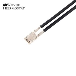
Many compact Thermal Motor Protectors use a bimetal element, sometimes combined with a current-sensitive heater, to detect excessive heat and interrupt the motor circuit. This design allows the device to respond to thermal conditions without requiring a separate electronic monitoring unit.
The Bimetal and Heater Mechanism
A bimetal strip consists of two bonded metals with different coefficients of thermal expansion. When its temperature rises, the metals expand at different rates, causing the strip to bend. In a thermal protector, this movement operates an electrical contact, changing it from the closed position to the open position.
In designs with a current-sensitive heater, current flowing through the protector generates additional heat through a heating element or the current-carrying bimetal itself. As the temperature rises, the bimetal eventually reaches its calibrated trip point and opens the contact. The snap-action mechanism provides rapid and decisive contact separation, helping interrupt the motor circuit when the specified thermal threshold is reached.
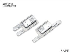
The 2MPE/5APE series is an example of a Thermal Motor Protector designed with temperature- and current-sensitive characteristics. Its bimetal and heater construction supports thermal response under different operating conditions. The trip time can also be controlled through the device’s design and calibration, making it an important parameter when matching the protector to a motor’s thermal withstand characteristics.
How the Trip Interrupts the Burnout Sequence
The protective process can be summarized in four steps:
-
A fault condition, such as a locked rotor or sustained overload, generates excessive heat in the motor or protector.
-
The bimetal temperature rises and reaches the calibrated trip point, causing the contact to open.
-
The open contact interrupts current to the motor, helping limit further winding temperature rise and reduce the risk of insulation damage.
-
After cooling, the protector either resets automatically or remains open until manual intervention, depending on its reset design. Self-holding configurations may require a separate reset condition.
A Thermal Motor Protector does not detect insulation failure itself. Instead, it responds to thermal conditions that may lead to motor burnout. If the trip response is too slow, winding insulation may be exposed to damaging temperatures. If it is too sensitive, normal starting or operating conditions may cause nuisance tripping. Selecting the appropriate trip temperature and response time is therefore essential to effective motor thermal protection.
How Does Trip Time Need to Match the Motor’s Thermal Withstand?
A Thermal Motor Protector is effective only when its trip time matches the motor’s thermal withstand limits. A protector with the correct trip temperature but a slow response may allow the winding to overheat during a locked-rotor event. Conversely, a response that is too fast may cause nuisance tripping during normal motor startup.
The Inherent Inverse-Time Relationship
Thermal protection generally follows an inverse-time relationship: as current increases, the acceptable trip time decreases. This reflects the motor’s thermal response under different load conditions. During a locked-rotor event, current may rise several times above the rated value, leaving less time before thermal damage occurs. Under a moderate overload, the temperature rises more slowly, allowing a longer response time.
Protectors with combined temperature and current sensitivity can reproduce this relationship through their physical construction. Higher current generates more heat in the internal heating element or current-carrying component, accelerating the bimetal element’s rise to its trip temperature. This results in a shorter trip time at higher current levels without requiring a separate electronic timing circuit.
Reading a Trip-Time Specification
A trip-time specification is meaningful only when its test conditions are clearly defined. For the 2MPE/5APE series, published parameters include an operating temperature range of 50°C to 170°C and a trip-current range of 1 A to 30 A. The specified trip time ranges from 4 to 10 seconds under defined test conditions, with customized requirements available.
This distinction matters when evaluating motor thermal protection. A trip time of “4–10 seconds” is not a universal performance claim; it must be associated with a specific test current and temperature condition. When comparing Thermal Motor Protectors or preparing an OEM purchase specification, confirm the following:
- The test current at which the trip time is measured, expressed as an absolute ampere value or a multiple of the rated current.
- The ambient temperature during testing.
- Whether the protector is tested in free air, mounted against a heat source, or installed in a representative motor assembly.
- The reset configuration, including automatic reset, manual reset, or self-holding.
Without these details, a trip-time value cannot reliably establish whether a protector is suitable for preventing thermal damage in a specific motor.
Matching Trip Time to Motor Data
The motor manufacturer’s thermal withstand data, often presented as hot and cold thermal limit curves, indicates how long the motor can tolerate a given current before thermal damage occurs. The protector’s trip response should remain within the motor’s thermal limits while allowing normal starting conditions to avoid nuisance tripping.
In practice, this matching process requires evaluating the motor’s full-load current, locked-rotor current, winding insulation class, and expected ambient temperature. The protector’s current rating, trip time, and temperature calibration must be considered together. A Thermal Motor Protector suitable for an intermittently operated automotive wiper motor may not be appropriate for a continuously rated appliance motor, even if their nominal current ratings appear similar.
What Role Does Mounting Location Play in Burnout Prevention?
A Thermal Motor Protector can only respond to the temperature transferred to its sensing element. If its mounting position does not allow it to track winding temperature accurately, its trip response may not reflect the actual thermal condition of the insulation.
Embedded and Surface-Mounted Configurations
Two common mounting approaches are used in motor thermal protection:
- Embedded or in-winding placement: The protector is positioned in direct or close thermal contact with the winding end turns. This allows it to respond more directly to heat generated within the motor winding, where insulation degradation can occur.
- Surface-mounted or housing-mounted placement: The protector is attached to the motor shell or a mounting bracket. Although this arrangement may simplify assembly, heat transfer from the winding can create a temperature difference and delay the protector’s response.
IEC 60730-2-22 addresses thermal motor protectors as controls whose protective performance depends on proper installation and fixing in or on the relevant motor. Their suitability must therefore be evaluated in the intended motor assembly rather than solely through standalone component testing. The standard’s applicability should also be confirmed against the product classification and intended application.
Thermal Lag and Why It Matters
When significant thermal resistance exists between the winding and the protector, the winding may reach a damaging temperature before the sensing element reaches its calibrated trip point. Although the protector may eventually open the circuit, the delay could allow excessive thermal stress to continue. This explains why a protector that performs well under controlled bench-test conditions may respond differently when installed in a motor with a different thermal path.
For compact Thermal Motor Protectors used in appliance and automotive motors, their small size and sealed-sleeving options can facilitate installation close to the winding or motor frame. The 2MPE/5APE series, for example, offers sealed sleeving described as varnish-proof, supporting applications involving winding impregnation processes. Compatibility with the specific varnish or resin should be verified before selection.
How Do You Select a Thermal Motor Protector for a Specific Motor?
Selection is not simply a matter of choosing the highest-rated protector or the widest temperature range. It requires matching four key variables: current, temperature, trip time, and mounting conditions.
A Selection Sequence
The following sequence outlines the information a protector supplier typically needs to recommend or customize a suitable device:
- Define the motor’s electrical operating conditions: rated voltage, rated current, and current characteristics during normal operation and relevant fault conditions.
- Define the thermal limits: winding insulation class, maximum permitted winding temperature, and ambient temperature range around the motor.
- Identify the fault conditions requiring protection, such as locked rotor, sustained overload, or overheating caused by abnormal operating conditions. Open-phase protection should be evaluated separately if required.
- Define the mounting interface: whether the protector will be embedded in the winding, attached to the motor frame, or mounted on a bracket, along with the required lead length and terminal type.
- Specify the reset behavior: automatic reset for applications that permit automatic recovery, or manual/self-holding reset when the fault should be investigated before restarting.
- Verify the protector’s trip time at the relevant current and temperature conditions against the motor’s thermal withstand data.
The 2MPE/5APE series specifications can be evaluated against these requirements. The published operating temperature range is 50°C to 170°C, with a tripping-current range of 1 A to 30 A and temperature tolerance options of ±5°C and ±7°C. Electrical ratings include 10 A at 250 V AC and 18 A at 125 V AC. For the 5APE variant, the reported DC ratings are 20 A at 12 V DC or 10 A at 24 V DC. These values provide a starting point for selection, but must be checked against the applicable variant, trip-time test conditions, and mounting configuration.
Customization and Commercial Considerations
For OEM and wholesale programs, a Thermal Motor Protector is often customized to match the motor design rather than selected solely from a standard catalog. Typical customization options include:
- Trip temperature and reset temperature.
- Trip current and trip time.
- Terminal type, lead wire length, and lead wire insulation rating.
- Sealed sleeving for compatibility with specified varnishes or fluids.
- PTC heating element options for self-holding or time-delay functions, depending on the design.
These options affect more than the physical configuration. PTC-assisted self-holding, for example, can keep the protector open after a fault even when the bimetal element has cooled. This can prevent repeated restart attempts under a persistent fault. Such behavior may be desirable when unattended restart must be avoided, but unsuitable for appliances designed for automatic recovery.
How Does a Thermal Motor Protector Compare with Other Protection Devices?
A Thermal Motor Protector is one layer in a motor protection system, not a replacement for every other protective device. Understanding the differences helps prevent protection gaps and unnecessary overlap.
| Device | Primary Sensing Input | Typical Role | What It Does Not Do |
|---|---|---|---|
| Thermal Motor Protector (bimetal, temperature and current response) | Local temperature and heat generated by current | Provides localized thermal protection against motor overheating; can be embedded in or closely coupled to the winding | Does not provide branch-circuit short-circuit protection on its own |
| Thermal overload relay | Current, which heats an internal bimetal element | Provides external overload protection in a motor starter; typically works with a contactor to interrupt power | Does not directly measure winding temperature; uses current as an indicator of motor heating |
| Motor protection circuit breaker (MPCB) | Current, through thermal and magnetic trip elements | Combines overload and short-circuit protection in a branch-circuit device | Does not directly sense winding temperature and may not detect overheating caused by poor cooling at normal current |
| PTC thermistor system | Winding temperature through embedded thermistors | Monitors winding temperature through a separate evaluation unit; the response threshold depends on the thermistor characteristics | Requires a monitoring relay or controller to initiate shutdown; the thermistor does not interrupt current by itself |
Reading the Comparison Correctly
The table is not a ranking of protection devices. A thermal overload relay and an MPCB serve starter-level and branch-circuit functions that a compact Thermal Motor Protector is not designed to replace. Conversely, a current-based MPCB may not detect winding overheating caused by restricted cooling when the motor current remains within its expected range.
The practical value of a Thermal Motor Protector lies in its proximity to the heat source and its response to both local temperature and current-generated heat. In small, cost-sensitive, high-volume applications—such as appliance motors, automotive accessory motors, and compact pumps—an embedded bimetal protector can provide localized thermal protection closer to the winding than a device installed in the control panel.
Bimetal vs. PTC: A Brief Note
Bimetal protectors and PTC thermistors both respond to temperature, but they operate differently. A bimetal protector is a self-contained switching device that opens the circuit when its trip condition is reached. Automatic-reset models can close again after cooling to their reset temperature. PTC systems, by contrast, require a separate monitoring relay or controller to initiate shutdown and manage the reset process. Neither technology is universally superior; the choice depends on whether the motor design requires a self-contained protective switch or a monitored temperature signal.
Conclusion
A Thermal Motor Protector helps prevent motor burnout by responding to excessive temperature and current-generated heat before winding insulation is damaged. Reliable protection depends on matching trip time to the motor’s thermal limits, choosing the right mounting position, and specifying suitable reset behavior.
For OEM and wholesale applications, Wuyue offers 2MPE/5APE series options with configurable trip temperatures, current ratings, terminals, and self-holding functions. Contact Daoan Chemical to discuss your motor requirements, request technical specifications, and evaluate a suitable configuration.